| |
|
|
- Overview
|
ELECTRIC VALVE/DAMPER ACTUATOR (APM-VA SERIES) :-
APM-VAM or APM-VAO is reversible geared motors used to operate dampers or valves in Electric Modulating Circuits. These electric actuators are designed to meet the requirement of damper control, valve control applications where it is generally required to drive the load through less than one complete revolution either direction and to stop instantaneously at any point of the stroke. Such devices, sometimes also called as Modulating Motors are extensively used for HVAC, Valve, Boiler Damper applications. The VAM series comes with manual movement, while VAO is without manual adjustment option. These are for the heavy duty application where the torque is a maximum of 2000 Kg-cm at a speed of 0.2 RPM.
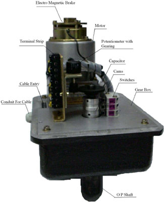
CONSTRUCTION:-
These actuators consist of our reversible, continuous duty (S1) four-pole motor, of 90Watts connected to the output shaft of the unit through a series of precision hobbed gears. The motor is IP 40. The gear train is sealed with high grade and high temperature stable grease, thereby ensuring permanent lubrication. Cam operated limit switches stop rotation of the output shaft at predetermined CW and ACW limit of travel. The stroke angle is factory set but can also be altered at field
.
|
|
- Features
- Stroke is fixed at 900, 1600, or 2700 and is also field adjustable. (Multi-turn can also be provided).
- Models can also be fitted with potentiometer for feed back and proportional 4-20mA control in conjunction with extended control.
- Available with internal cam adjusted auxiliary switches.
- Electro-magnetic brake can also be provided for instantaneous stop and prevent any back drive from the valve.
- The motor winding has thermal switches to prevent burn out when over heated. The motor starts again only when it is cooled.
|
- Specification
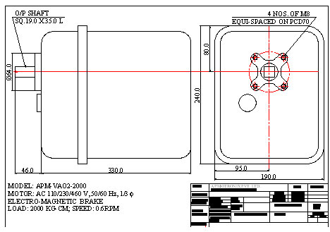
Electrical & Mechanical Specifications: (FOR BASE MOUNT, PLEASE CALL US):
- Motor Supply Voltage : 110/230/460 VAC, 1/3 Φ, 50/60 Hz.
- Power Consumption : 90 Watts (max.)
- Brake Supply Voltage : 230 VAC, 1 Φ, 50/60 Hz.
- Stroke : Factory set at 900.
- Auxiliary Switch : 230VAC, 16 Amps.
- Potentiometer (POT) :135 Ω / 1.0 kΩ, 1 Watt, Single turn (The maximum permitted power dissipation for this POT is 1W for 900).
- Positioner : 4-20mA I/P & O/P.
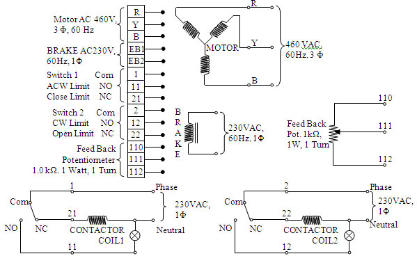
Electrical circuit:
Installation:
TESTING:
- Before mounting or wiring or setting the limit switch and potentiometer, please run the actuator/motor with the aid of our electrical circuit drawing (during this operation, by-pass all the external circuitry). Please bear in mind that by-passing the external electrical circuit or rated power supply directly to motor & brake, the limit switches will not control the actuator/motor rotation and hence will permanently damage the potentiometer (to avoid this dis-engage the potentiometer gear/pinion). Remove the enclosure of the unit for setting the cams, switches, potentiometer, and for wiring the terminal block.
- Check the actuator/motor rated operating voltage; for the 3 Φ motor, input the supply Red (R), Yellow (Y), and Blue (B) to the corresponding R,Y, B at the connector/terminal block. Simultaneously, power the electromagnetic brake at the rated voltage. Viewing from the actuator output shaft, it should rotate in the ACW direction. To reverse the direction of rotation, interchange any two inputs of the power supply.
Caution: If the limit switches (230VAC, 16Amps.) and potentiometer are factory set (generally positioned in the intermediate), then run the actuator momentarily. By checking the resistance between 110 & 111 or 111 & 112 ensure that the potentiometer is not damaged even for this momentary operation. For factor of safety, please cut off the actuator/motor and brake supply at least 5% before the rated extreme resistance values. Over-driving the actuator will damage the potentiometer.
MOUNTING:
- Please check our mechanical dimensional drawing for the mounting details. Suitable bracket has to be used to mount the actuator unit to the valve input without any mis-alignment. Any mis-alignment in the mounting will be reflected on the output shaft, gear train and the motor. This misalignment will permanently affect the life of the Gears, Shaft, Ball Bearings. In such a situation, the actuator may not even drive the designed load / torque. A flexible coupling avoids damage to an extent.
- The unit has to be mounted with 4 numbers of M8 screws of appropriate length. Do not use lengthy screws as they might damage the gear box housing (the depth of tap in the housing is 12.0mm).
SETTING:
After mounting, follow our circuit drawing for wiring the actuator. Please note that the rated operating voltages will be different for Motor, Brake, and Switches. The setting of the limit switches and the potentiometer is very critical to the functioning of the actuator.
- Cams: Lightly loosen the M4 grub screws on cam 1, so that the cam is free on the shaft. Run the actuator in the direction until the valve is near to the closed position. Now “Inch” the supply, the actuator runs and stops momentarily. Repeat the inching until the valve is completely closed. Cut off the power supply. Now set the Cam 1 so that it operates the limit switch 1. To set the cam, operate switch 1 with the cam pressed against the switch roller until “click” sound is heard. Without disturbing this cam position, tighten the M4 grub screws of cam 1. During subsequent reversal to set cam 2, the remaining of the M4 grub screws on cam 1 can be tightened.
- Reverse the direction of rotation of the actuator by reversing any of the two wires of the 3 Φ power supply. Follow step 1 for setting Cam 2 for open limit.
- To ensure the limits setting of the switches 1 & 2, follow steps 2 & 3 until the switches operate or the valve closes/opens (whichever is earlier). Do not loosen the grub screws on the cam. Fine adjustment of the cams has to be done very carefully.
- POT: After setting of the cams, the potentiometer (POT.) has to be set. For this, position the valve at the close position (remember switch 1 has to operate to stop at the close position). Set the POT such that the resistance between 110 & 111 is 5% of the rated POT resistance. Engage the POT pinion with the POT gear on the output shaft. Tighten the grub screws of the pinion & gear. Tighten the POT on to the POT clamp. [Note: Ensure that if you reverse the direction of rotation of the actuator (towards valve opening) the resistance between 110 & 111 should increase (otherwise the POT will be damaged). If the resistance decreases, cut off power supply immediately and in step 4, set the resistance between 110 & 111 to 95% of the rated POT resistance (when switch 1 is operated)].
- The POT gearing is designed for the particular stroke angle of the actuator. Changing this ratio alone, might damage the POT.
MAINTENANCE:
- The gear box is greased for life. Provision (grease nipple) for greasing is also provided, just in case.
- In case of actuator malfunction, check the input electrical specifications for the rated values of the motor, brake, switches. Check if the motor is heated, if so, allow it cool so that the thermal switches connected to the winding will run the motor. If these are normal, then remove the enclosure, dis-engage the POT. Directly power the motor and brake simultaneously at the rated values, by-passing the external electric circuit. If the actuator runs, properly then it is the problem with either the POT or external circuit. (if the actuator fails to run, then check for any obstruction in the valve path or mis-alignment at the mounting due to wear & tear. Dismount the actuator and run the actuator). To check the POT, manually check the POT resistance from minimum to maximum. If there is no abnormality, then there might be problem with the external circuit.
PRECAUTION:
- Cut off the power supply, if the unit has to be dissembled.
- The actuator has to be integrated to the load without misalignment. Any misalignment will permanently affect the life of the Gears, Shaft, Ball Bearings. In such a situation, the actuator may not even drive the designed load / torque. A flexible coupling avoids damage to an extent.
- In the off condition, brake is applied on the motor to prevent any over-drive because of the inertia. So do not drive the Shaft with the wrench, as it might damage the Gears and Brake.
- The single turn (generally 2600) POT is driven by gear ratio to match the factory set stroke angle. Over-riding the stroke angle will permanently damage the potentiometer. This occurs in VAM (manual movement option), where the customer while manually adjusting may not observe the resistance value of the potentiometer.
- In case of 3Φ power supply, the 1Φ switches should be operated through a contactor coil. As such, the switches can limit the actuator end limits.
- Always assemble the actuator enclosure to avoid any damage/malfunction of the components/sub-assemblies.
|
|
|
|
